


Woven fiber reinforced plastics are receiving growing attention from the transportation industry because of their high performance to weight ratio. Due to its good geometric conformability, woven glass fiber reinforced plastics (GFRP) or carbon fiber reinforced plastics (CFRP) is most suitable for complex part geometries. The highly-automated composite thermoforming process of prepregs, as shown in Fig 1, was developed to reduce cycle time and manufacturing cost.
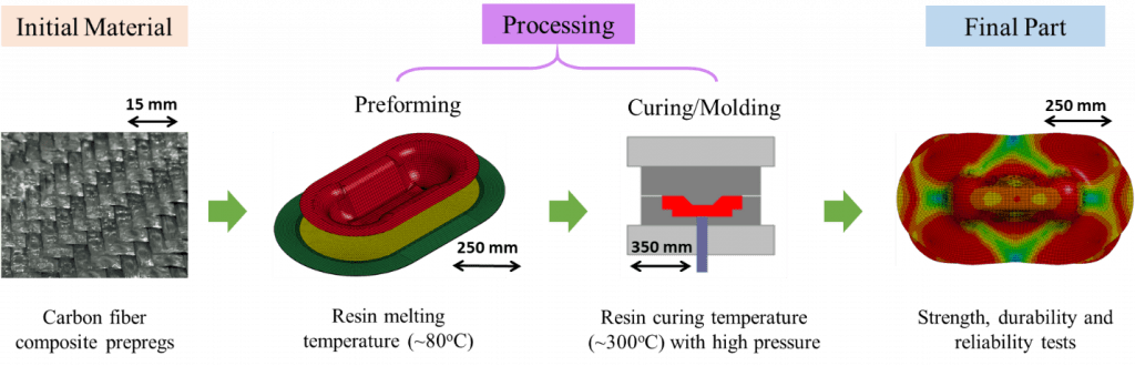
Fig. 1. Schematic of the carbon fiber composite thermoforming process
Material used in the first preforming step is the stacked flat layers of prepregs, which are woven CFRPs impregnated with uncured thermoset resin in desired fiber orientations. These layers are heated above the resin melting temperature to fully soften the prepreg and form into the part shape on a press. The formed part is then cured to harden the resin for the permanent shape.
Processing modeling of woven fabric composites Woven fabric composites usually undergo large in-plane shear deformation in the preforming process. The reorientation and redistribution of yarns after forming results in a significantly anisotropic material behavior. A non-orthogonal constitutive model to characterize this anisotropic behavior of woven composites has been developed. It enables us to accurately predict the yarn orientation and defects occurring in the preforming, such as wrinkles (Fig.2).
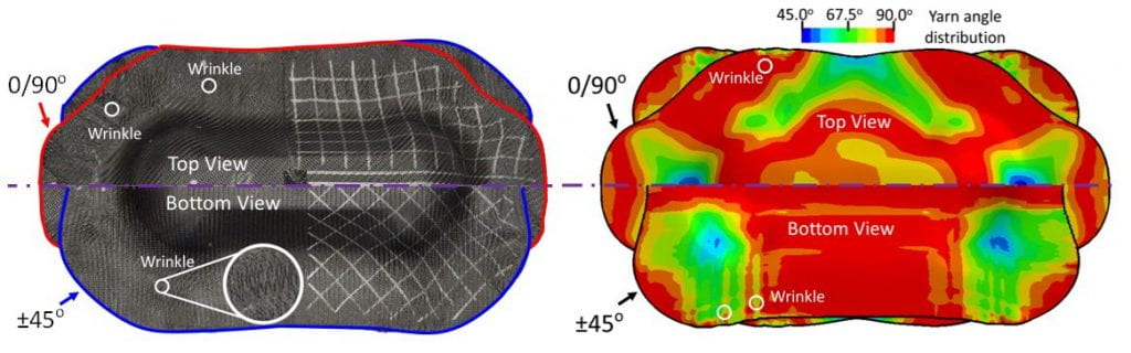
Fig. 2. Comparison between experiment and simulation with non-orthogonal constitutive model
Constitutive Law in the MAT_COMPRF
Our non-orthogonal model has been incorporated into the LS-DYNA® software as MAT_COMPRF (MAT_293) through the joint effort of this academic and industry team (see publication here under “Composites Forming“).
MAT_COMPRF enables users to directly input experimental data to define the stress-strain curves, as well as the shear locking angle, which indicates whether the shear deformation reaches the extent that the rotation resistance between warp and weft yarns is no longer small compared to the tensile modulus of the material. These material properties could be obtained via uniaxial tension, bias-extension, and bending tests in [5]. The flowchart of the model is shown in Fig. 3.
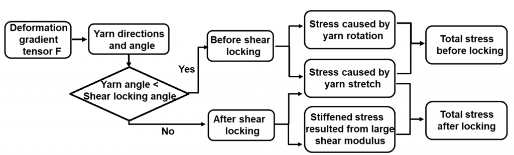
Fig. 3. Calculation flowchart of the LS-DYNA MAT_COMPRF.
In the material subroutine, the warp and weft directions for each element are calculated from the deformation gradient tensor. If the angle between the warp and weft yarns are smaller than the shear locking angle, then the small shear modulus condition will hold. If the angle between the warp and weft yarns reaches to the shear locking angle, the resistance for further shear deformation will greatly increase because the contacted fiber yarns stiffen the woven structure. In this situation, the shear resistance of the model will increase automatically to avoid further large shear deformation.
Experimental Validation
The double-dome test, as shown in Fig. 4, was conducted by our industrial collaborator Ford and simulated in LS-DYNA® by our team to demonstrate the capability of the MAT_COMPRF for 3D shape forming regarding different yarn orientations and stacking sequences. The sheet was modeled by reduced integrated shell elements. Each element is about 4 mm × 4 mm with five through-thickness integration points. The punch, binder and die were modeled by rigid shell elements.

Fig. 4. Experimental setup for the double-dome test.
The simulation results in the upper-right quarter of Fig. 5 show that the MAT_COMPRF material model is capable of accurately predicting the physical experiments regarding the yarn angle distribution and blank draw-ins. For instance, the deviation of the maximum draw-in distance is about 7 mm (49 mm in experiment versus 42 mm in simulation). For comparison, an orthotropic material model (MAT_002) is utilized in another simulation whose result is shown in the upper-left quarter of Fig. 5 in the same scale as non-orthogonal model and experiment results. Since the orthotropic model cannot track the material property change during the yarns’ rotation, the corresponding simulation has a maximum draw-in deviation of 24 mm, not capturing the overall process behavior.
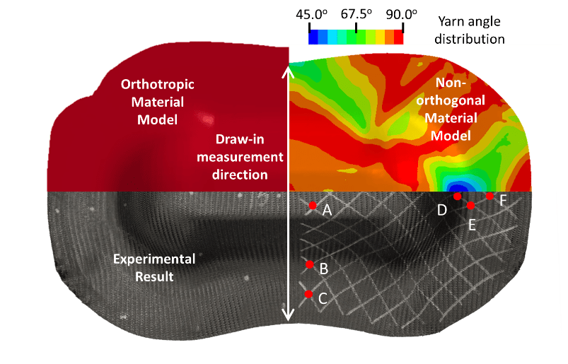
Fig. 5. Simulation and experimental results comparison of deformed geometry and yarn angle distribution for double dome preformed part of ±45º single layer woven prepreg.
In the MAT_COMPRF model, the yarn angle is defined as an output variable, while MAT_002 does not have the capability for direct visualization. For clarity, Table 1 compares the resulting shear angles at various locations obtained from the experiment and simulations. Again, it shows that the current model has improved the prediction accuracy.
Table 1. Resulting yarn angles from the single-layer case

The ICME Approach
Our above work is part of the Integrated Computational Materials Engineering (ICME) effort to develop, integrate and implement simulation tools for Carbon-Fiber Reinforced Polymer (CFRP) composites, which integrates different modeling and simulation tools into one system that links composite material design, processing and design optimization to accelerate the manufacturing of CFRP components (Fig.6).
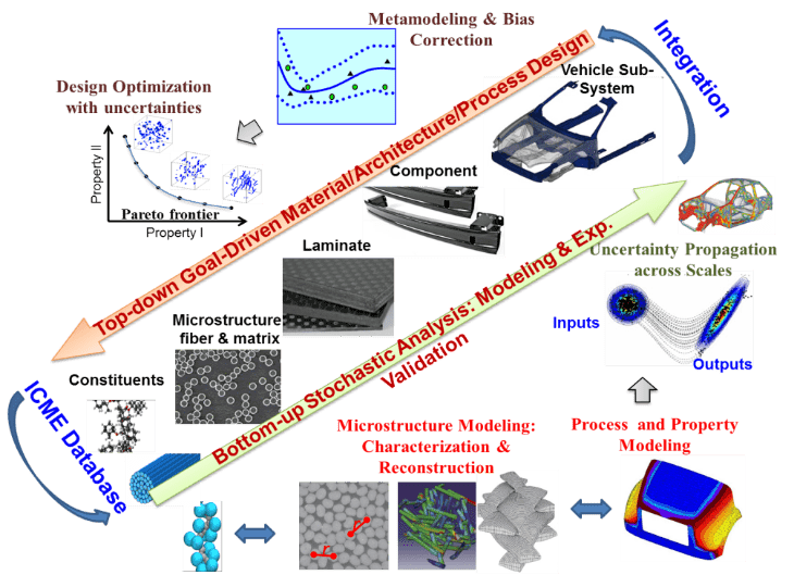
Fig. 6: ICME framework for CFRP (in collaboration with Profs. Wei Chen, Isaac Daniel and Wing K. Liu at Northwestern, Ford, Dow and LS-DYNA).
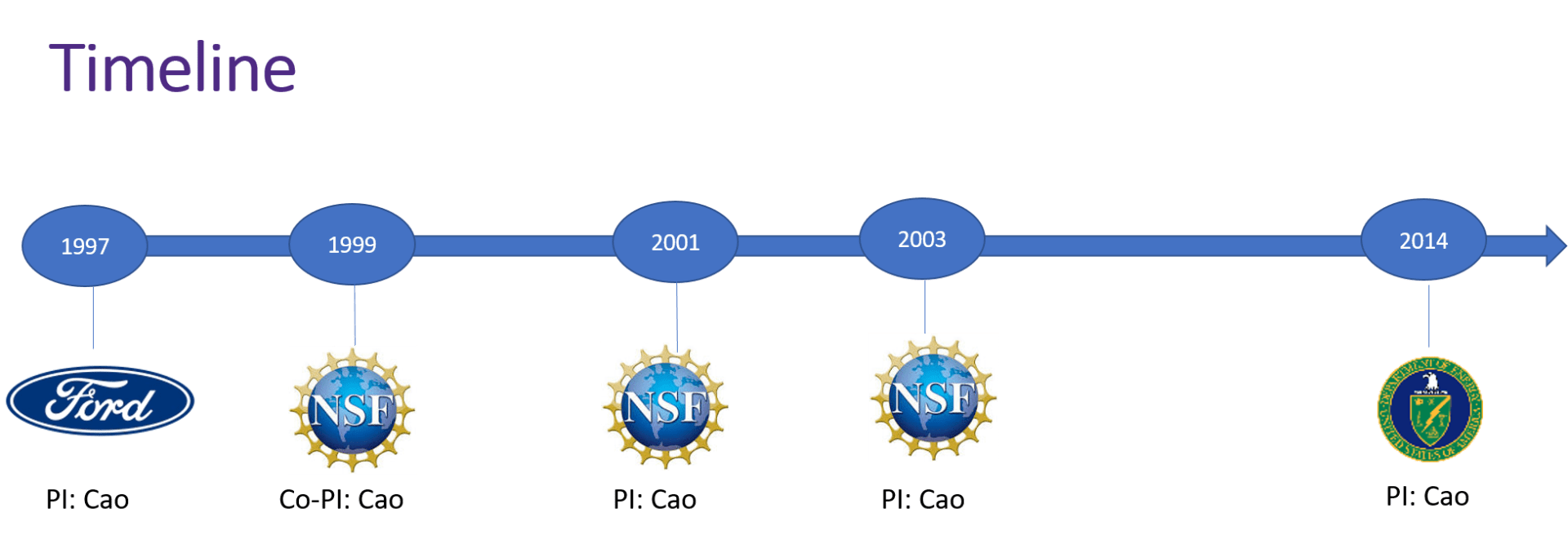
Our Timeline
Our Journal Publications
See our publications > Composites Forming for details.
Awards Received
2019, Distinguished Achievement Team Award, DOE EERE Vehicle Technologies Office, 2019 – to recognize outstanding industry-university-government partnerships, with Ford, Dow Chemical and NIST.
Our Sponsors
This work was supported by the Office of Energy Efficiency and Renewable Energy (EERE), U.S. Department of Energy, under Award Number DE-EE0006867.