

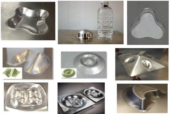
 DSIF is a relatively new concept for flexible sheet forming, in which a sheet blank is clamped around its periphery and gradually deformed to a complex 3D freeform part using two strategically aligned stylus-type tools that follow pre-described toolpaths. The two tools, one on each side of the blank, can form a part with both concave and convex shapes incorporating highly-detailed features with excellent surface finish. In generalized DSIF, the top and the bottom tools typically have three degrees of freedom but can have up to six degrees of freedom. Their motions can be independently controlled or synchronized to achieve different desired outcomes. Furthermore, hybrid DSIF processes, such as electrically-assisted DSIF or laser-assisted DSIF, can be implemented to form hard materials such as titanium alloys.
Video: Incremental Forming Methodology

What Are the Advantages of DSIF?
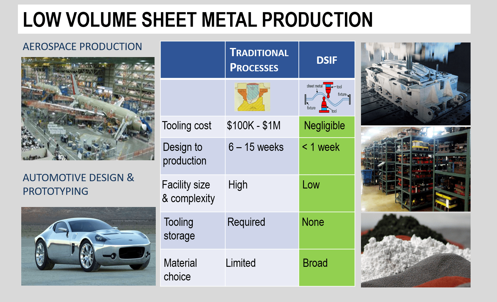
Sheet forming processes have been widely used in various industries, including automotive, aerospace, medical, appliance manufacturing, etc. In all of these industries the trend of ever-tighter product cycles and the demands for personalized products have put increasing pressure and urgency on having a means to rapidly generate 3D sheet products either for prototyping or for real-applications. Low volume production and prototyping of sheet metal parts is typically performed today using conventional forming operations such as die stamping and hydro-forming. These processes require part-specific die sets that are cast and precision machined, can weigh multiple tons, and can cost up to $1M each depending on part size and complexity. As a result, these processes are considered expensive and slow for fabricating sheet parts in low volume.
DSIF presents a complete dieless forming process with high process flexibility and high controllability of geometric accuracy. The cycle time from a design to a physical product can be as short as several hours compared to the current standard of 6-15 weeks. The substantial economic and societal benefits include:
- Reduced manufacturing costs – eliminates the need for geometry-specific tooling, which can be very expensive, in some cases about $1M per tooling/die set.
- Shorter cycle times – reduces the design-to-part cycle time from the current 6-15 weeks down to less than 1 week, enables digital manufacturing achieving at least a 10x cost reduction.
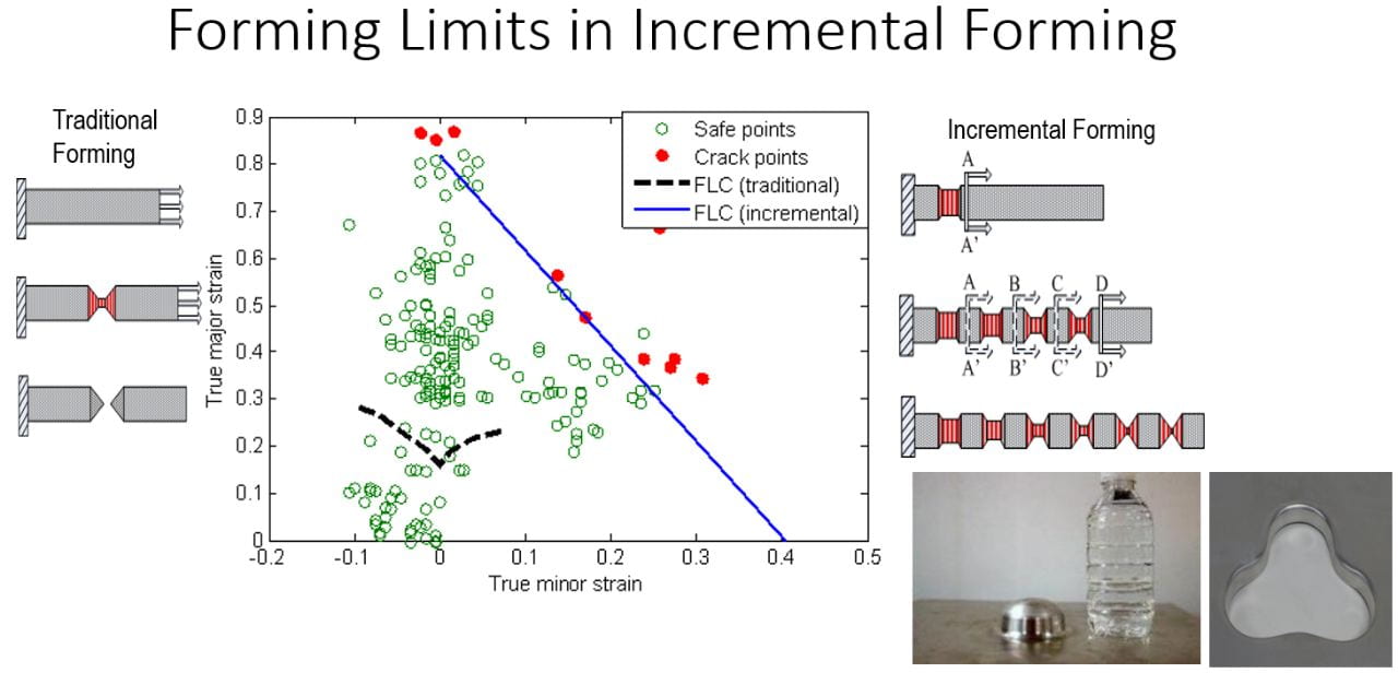
- Higher material formability – changes the deformation mode from uniform elongation in the conventional processes to distributed local deformation in DSIF, hence moving the failure limit towards the fracture limit, resulting in an increase of formability of up to 4x compared to conventional sheet forming processes.
- Lower energy costs – Traditional sheet metal processes are not energy efficient for low-volume production as they require heavy dies (stamping dies easily weighs over 1 Ton), more material (material usage can be as low as 5% when milling aircraft parts), geometric restrictions (mostly axisymmetric in spinning) or are severely limited by thermal deformation (in directed energy deposition) or work envelope (in powder-bed additive manufacturing). DSIF is entirely dieless and is efficient in material usage (60-100%), scalable in size and versatile in geometry.
What Are the Challenges of DSIF?
As a relative new manufacturing process, industrial implementation faces the following challenges:
1) the ability to know the formability limit in this process;
2) the ability to get the geometry of the first part right;
3) the availability of having a turn-key operation, seamlessly from a CAD model to process planning and process execution; and
4) other operation issues such as forming time, process scalability, and surface finish.
Our Work to Address the Challenges
1. Formability: We concluded that the formability in DSIF was determined by the fracture limit and proposed the distributed damage theory, nickname “noodle theory”, to explain the phenomenon [Malhotra et al. 2012, JMPT]. Furthermore, by designing a tool path and forming sequence, enhanced formability in forming [Malhotra et al. 2011, CIRP] and flanging [Zhang et al. 2019, IJMF] can be achieved. Finally, as is known, material formability can be increased at an increased working temperature. Electrically-assisted DSIF was shown to improve the formability of Ti-6Al-4V alloys [Valoppi et al. 2016, CIRP]. More fundamental aspects of material behavior in electrically-assisted forming can be found here (under “Incremental Forming”). Based on our experience, we proposed a general Process-Constraints-Mechanism-Innovation (PCMI) framework [Cao and Banu 2020, JMSE] to guide process innovation.
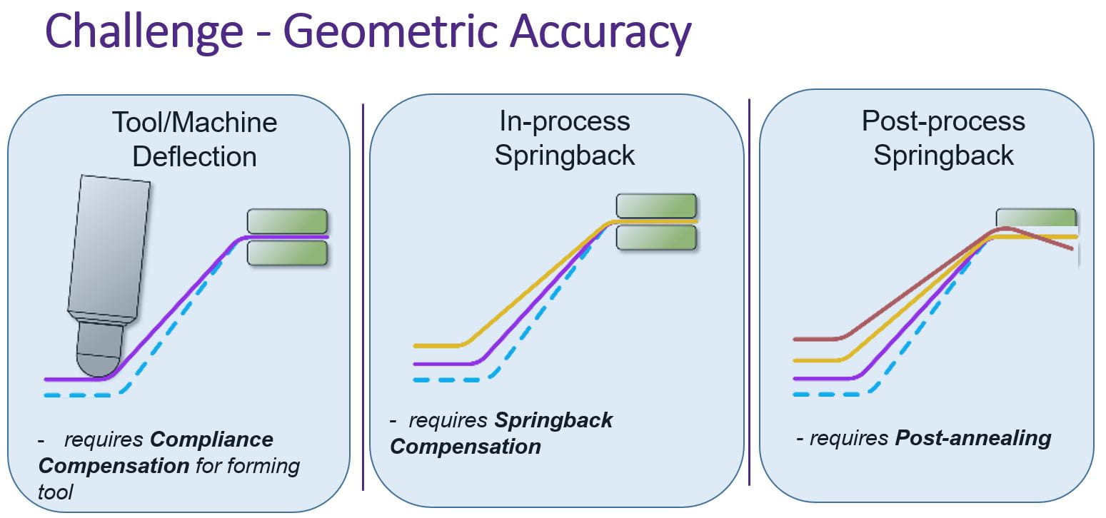
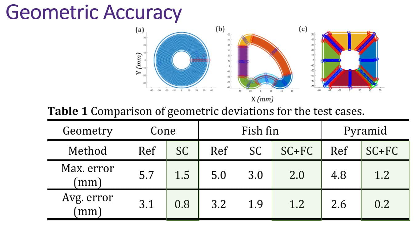
2. Geometry accuracy: We systematically analyzed the problem of geometry deviation and attributed it to three major causes (machine compliance, in-process springback, and post-process springback) as illustrated in the figure below. We have further developed and implemented compliance compensation for the forming tool and contact force control for the supporting tool [Ren et al. 2018, CIRP]. More importantly, the in-situ springback compensation method was developed based on real-time force and position sensing combined with the mechanics-driven model generated by a series of FEM simulations at control points identified through a geometry partition analysis [Ren et al. 2019, CIRP]. The approach is general and suitable for a variety of geometries as demonstrated below, in which SC stands for ‘springback compensated’ and ‘FC’ stands for ‘force controlled’.
3. Turn-key operation: The autonomous software developed in our group, called AMPL Toolpath, combined with the hardware system can achieve a one-touch goal and hence lower the barriers for implementing the technology, for example, in the maker space. The implementation can achieve the goal of handing the technology into the hands of many.
4. Other aspects: We performed the preliminary study on the fatigue life of DSIF-ed workpiece which is found to be longer than the original workpiece and longer than that from a single-point incrementally formed workpiece [Xu et al. 2014, Mfg Letters]. A more systematic study is needed. We also proposed the concept of combining two different DSIF forming strategies to reduce forming time and to generate desired surface texture, and the possibility of using waterjet in micro-incremental forming (see publications below).
Our Collaborators
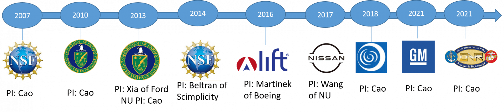
Our Timeline
Our lab has participated in the following projects:
Our Journal Publications
See our publications > Incremental Forming for details.
Awards Received
2020, ISFA Best Application Paper Award at the ISFA 2020 – “Kinematic Calibration and Data-Based Error Compensation of a Parallel Robot-Based Incremental Sheet Forming Machine”
Our Patents
- Roth, J. and Cao, J. “Electrical-assisted Double Side Incremental Forming and Processes Thereof”, US Patent No. 8,741,079 B2, June 3, 2014.
- Malhotra, R. and Cao, J. “System and Method for Accumulative Double Sided Incremental Forming”, US Patent No. 9,168,580, October 27, 2015.
- Beltran, M., Cao, J. and Roth, J. “System and Method for Incremental Forming”, US Patent No. 9,221,091 B2, Dec. 29, 2015; US Patent No. 10,913,100, February 9, 2021.
- Ndip-Agbor, E. E. and Cao, J. “An Automated Toolpath Generation Method for Double Sided Incremental forming of Three Dimensional Freeform Shapes from Sheets”, US 2017/0227947 A1, 15/424.182.
- Zeng, Q., Ehmann, K., Ng, M.K. and Cao, J. “Incremental rotary rolling mill and method”, US Patent No. 11,077,477 B2, August 3, 2021.